- Statement of the Problem
- Schematic of Interfacing DHT Sensor with Serial LCD using ARDUINO
- Connection Diagram of Arduino with DHT22 and LCD
- Code for Interfacing DHT and LCD with Arduino
- Circuit Explanation
- Arduino UNO Board
- I2C Working and LCD Screen Serial Interfacing
- Serial Communication from Master to Slave
- Serial Pin out of Various Arduino Board
- Features
- Working Principle of DHT Sensor
- Feature Comparison Between DHT11 & DHT22
- Interfacing DHT Sensor using DHT Library
- Code Explanation
- Result
Statement of the Problem
In this article, we are going to see how to interface the DHT sensor using Arduino UNO and Monitor the temperature and humidity using serial communication protocol with an LCD. Different levels of temperature and humidity can be measured and it will be displayed in the LCD which is connected to the Arduino.
This article helps the reader to understand the interfacing of the LCD through serial communication with Arduino. The DHT (Digital Humidity and Temperature) Sensor interfaces with the Arduino and the result of the sensor is displayed in LCD through serial communication.
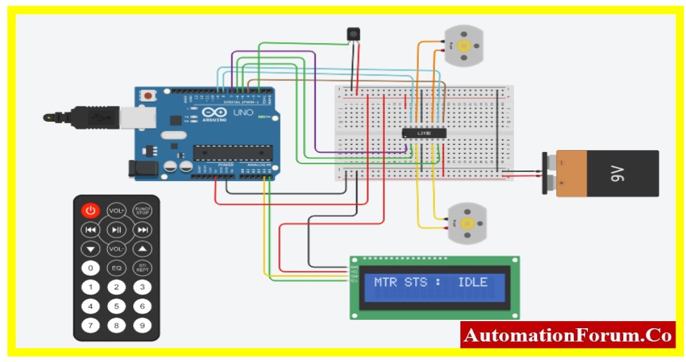
Schematic of Interfacing DHT Sensor with Serial LCD using ARDUINO
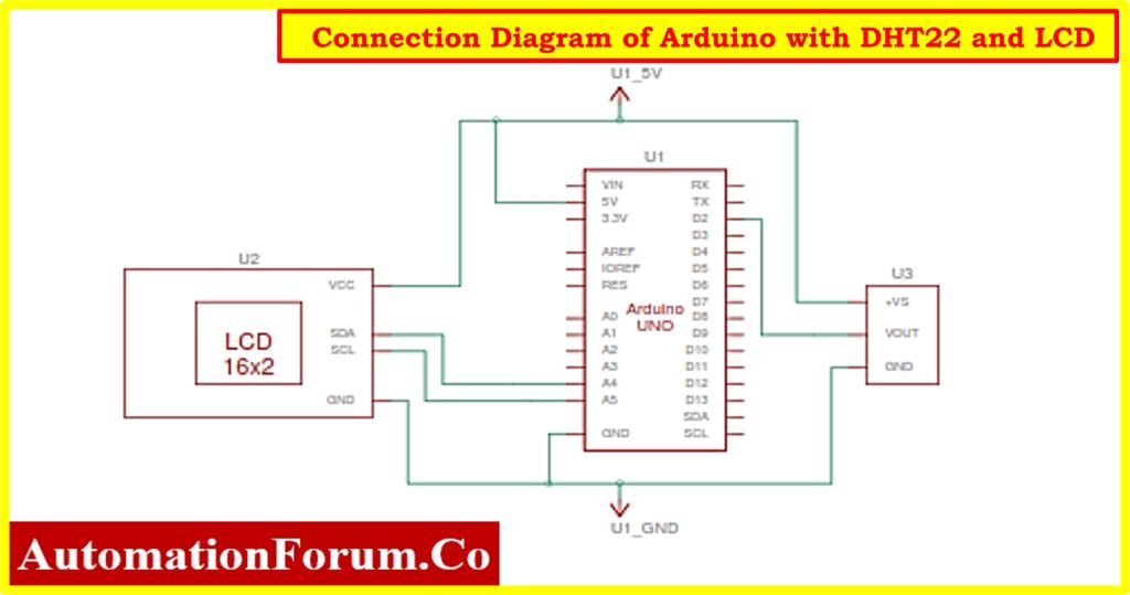
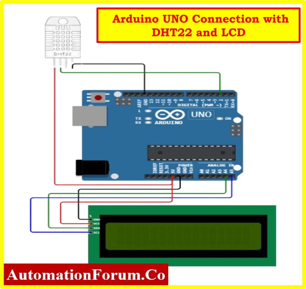
Connection Diagram of Arduino with DHT22 and LCD
Code for Interfacing DHT and LCD with Arduino
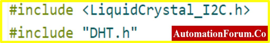
#include<LiquidCrystal_ I2C.h>
#include”DHT.h”
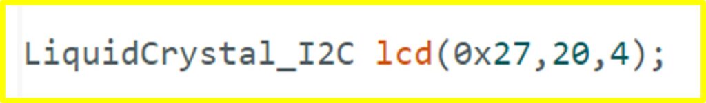
LiquidCrystal_ I2C lcd(0x27,20,4);
#defineDHTPIN2
#defineDHTTYPE DHT22
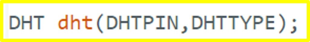
DHT dht(DHTPIN,DHTTYPE);
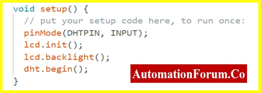
voidsetup(){
// put your setup code here, to run once:
pinMode(DHTPIN, INPUT);
lcd.init();
lcd.backlight();
dht.begin();
}
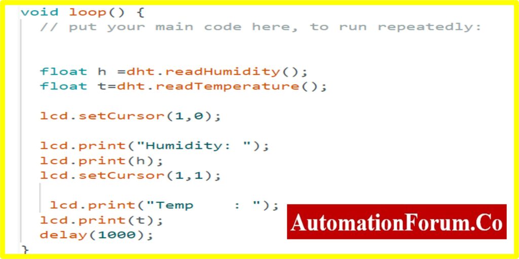
voidloop(){
// put your main code here, to run repeatedly:
lcd.setCursor(1,0);
float h =dht.readHumidity();
float t=dht.readTemperature();
lcd.print(“Humidity: “);
lcd.print(h);
lcd.setCursor(1,1);
lcd.print(“Temp : “);
lcd.print(t);
delay(1000);
}
Circuit Explanation
The above circuit consists of Arduino UNO, LCD Screen, and DHT sensor. The major part of this article is about interfacing Arduino with the DHT and LCD serial communication, the following content explains how to interface the sensor with Arduino and various parts of the Project.
Arduino UNO Board
The following link provides the reader with a detailed explanation of the Arduino.
I2C Working and LCD Screen Serial Interfacing
A thorough explanation of the pins and the process of connecting an LCD to an Arduino can be found at the following link.
Phillips was the first to introduce I2C communication. It has two wires, as was previously mentioned, and these wires will be connected to two devices. In this case, one device is referred to as the master and the other as the slave. A Master and a Slave should and will always communicate with one another. I2C communication has the benefit of allowing multiple slaves to be connected to a master.
Two lines are used in the I2C protocol for data transmission and reception: a serial data pin (SDA) that is used to transfer data between the two devices and a serial clock pin (SCL) that the Arduino Controller board pulses at regular intervals.
A single bit of data travels over the SDA line from the board to the I2C device as the clock line shifts from low to high, or the rising edge of the clock pulse. When the clock line continues to pulse, more and more bits are sent until an address consisting of seven or eight bits is formed, either as a command or as data.
Serial Communication from Master to Slave
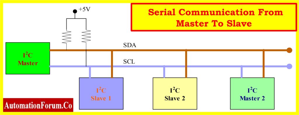
When this data is transmitted bit by bit. The device reacts to the request by sending its data back. If necessary, the board can be connected over the same line with the timing provided by the clock signal that the controller on SCL is still producing.
I2C is utilized in numerous applications, such as external EEPROM memory access and RTC (real-time clock) reading. Additionally, sensor modules like magnetometers and gyros also use it.
The I2C protocol communicates over two lines:
1. Serial Clock (SCL): This signal is a clock. On a clock tick event, data will be transmitted to other devices. This SCL line is under the control of the master device alone.
2. Serial Data (SDA): This is a data line used for data exchange between a slave and a master device.
A table listing the various boards and their matching I2C pins can be found below.
Serial Pin out of Various Arduino Board
| Arduino Board | SDA | SCL | SDA1 | SCL1 | SDA2 | SCL2 |
| UNO | SDA/A4 | SCL/A5 | ||||
| Nano | A4 | A5 | ||||
| GIGA | D20 | D21 | D102 | D101 | D9 | D8 |
| Mega & Due | D20 | D21 |
Only the master will have the ability to start a conversation at any given moment. The master must use a distinct address for each slave because there are multiple slaves on the bus. Only the slave who has that specific address will respond with information when addressed; the others remain silent. In this manner, we can communicate with numerous devices using the same bus.
I2C does not have set voltage levels. Flexible I2C communication allows devices powered by 5 volts to use 5 volts for I2C communication, while devices powered by 3.3 volts can use 3 volts for the same purpose. ln the event that two devices have different voltages. A 3.3V device cannot be connected to a 5V I2C bus. To match the voltage levels between two I2C buses, voltage shifters are used in this instance.
A transaction is defined by a set of conditions. The falling edge of SDA, which is referred to as the “START” condition in the diagram below and occurs when the master leaves SCL high while setting SDA low, is when transmission first starts.
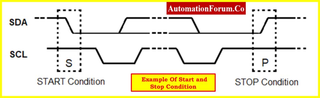
The hardware trigger that initiates the START condition is the SDA falling edge. Any devices connected to the same bus after that enter listening mode.The master leaves SCL high and releases SDA to go HIGH when the rising edge of SDA does the same, which is represented as the “STOP” condition in the above diagram. Transmission is thus stopped by the SDA’s rising edge.
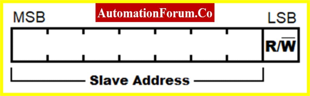
The R/W bit indicates which way the subsequent bytes will be transmitted; a high value indicates that the slave will transmit, and a low value indicates that the master will transmit.
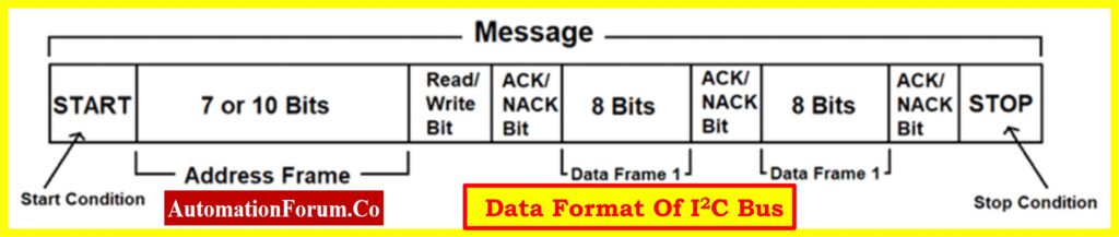
It takes eight clock cycles to transmit a byte since each bit is sent once per clock cycle. The ACK/NACK (acknowledged/not acknowledged) is held for the ninth clock cycle following each byte that is sent or received. Either the master or the slave, depending on the circumstances, generates this ACK bit. SDA is set to low for the ACK bit at the ninth clock cycle by the master or slave. Thus, if it is low, it is regarded as ACK; otherwise, NACK.
Only short-distance communication uses I2C communication. With its synchronized clock pulse for intelligence, it is undoubtedly somewhat dependable. This protocol is primarily used for data transmission to a master from sensors and other devices. It comes in very handy when a microcontroller needs to communicate with a large number of slave modules with the fewest possible wires.
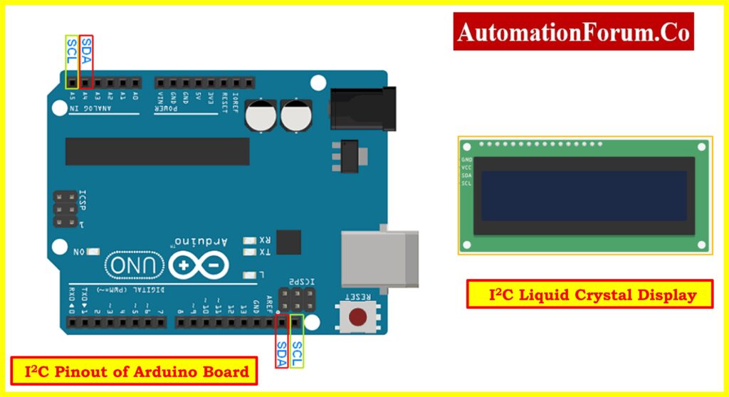
The above configuration shows the different pins used for I2C in Arduino UNO and serial LCD Display
This display eliminates the disadvantage of a parallel LCD, which requires eight pins on the Arduino board to function. The pins of the display are directly connected to an I2C adapter. The I2C pins only need to be connected, and they display minimal coding and a good library.
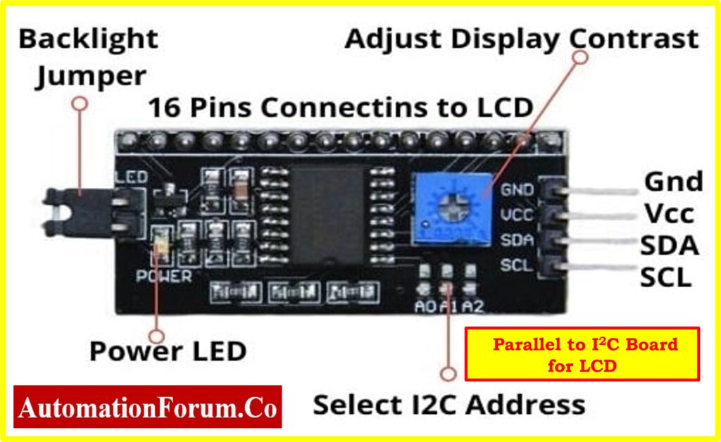
If the direct serial LCD is not available. The user can convert the parallel LCD into a serial LCD by connecting the above add-on board to the LCD. This will convert Parallel to serial communication for any device.
A serial I2C LCD adapter turns a 16 x 2 character parallel-based LCD into a serial I2C LCD that only requires two wires to operate. The PCF8574 chip, which is used in the adapter, functions as an I/O expander and uses the I2C protocol to communicate with Arduino and other microcontrollers. The same two-wire I2C bus can support up to eight LCDs, each with its address on the board. By soldering A0 A1 A2 pins, the default I2C address of 0X27 can be changed to any of the following addresses: 0X20~0X27.
Features
- The 16 x 2-character LCD can be controlled with just two wires.
- Up to eight LCDs can be connected and controlled by the same two-wire I2C bus.
- The LCD is compatible with the Arduino board.
- The adapter includes a 16-PIN male header connector for soldering to the LCD.
- The onboard potentiometer allows for contrast adjustment.
- A jumper can be used to turn on or off the backlight. The standard 5V voltage supply.
DHT Sensor
Digital Humidity and Temperature are referred to as DHT. A cheap digital sensor for measuring humidity and temperature is the DHT sensor. Any microcontroller, including Arduino and Raspberry Pi, can be easily interfaced with this sensor to measure temperature and humidity instantly.
The DHT sensors come in two varieties, which are as follows:
The specifications for these two sensors are as follows:
A cheap digital temperature and humidity sensor with a single-wire digital interface is the DHT22.It measures the air around it using a thermistor and a capacitive humidity sensor, then outputs a digital signal on the data pin (analogous input pins are not required).Although it is fairly easy to use, grabbing data requires precise timing. It can only provide you with fresh information once every two seconds.
Working Principle of DHT Sensor
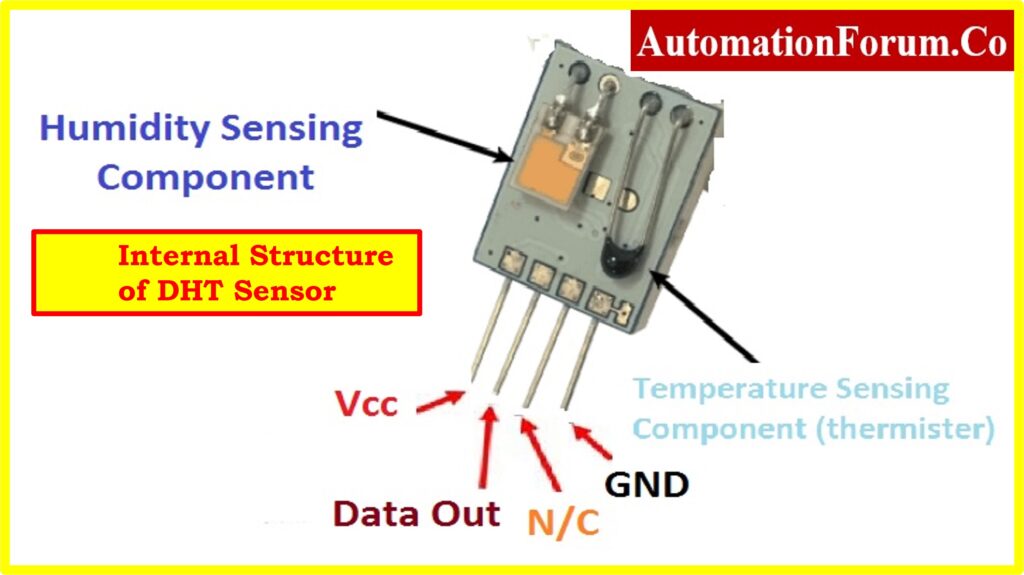
The DHT sensor is made up of a thermistor for temperature sensing and a capacitive humidity sensing element. The humidity-sensing capacitor’s two electrodes are separated by a dielectric substrate that retains moisture. Ashumidity levels fluctuate, so does the capacitance value.
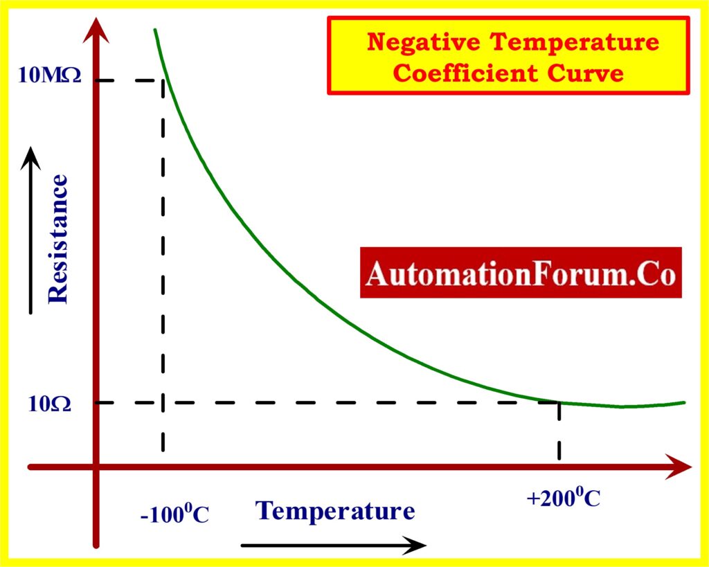
This sensor uses an NTC thermistor to measure temperature. NTC stands for “Negative Temperature Coefficient,” which indicates that as temperature rises, resistance falls, as seen in the graph below. Typically, semiconductor ceramics or polymers are used in the construction of this sensor to obtain a higher resistance value even for very small temperature changes.
The DHT11 and DHT22 sensors are made up of three primary parts. The analog signals from the two sensors are converted into a single digital signal by an 8-bit microcontroller, an NTC (negative temperature coefficient) thermistor, and a humidity sensor.
The 40 bits of data from the DHT11 and DHT22 sensors are formatted as follows:
1. 8 Bit data represents an integral portion of the Humidity value;
2. 8 Bit data represents a decimal portion of the Humidity value;
3. 8 Bit data represents an integral portion of the temperature value;
4. 8 Bit data represents a decimal portion of the temperature value; and
5. 8-bit data represents the checksum.
The final 8 bits of “8 Bit integral Humidity data + 8 Bit decimal Humiditydata + 8 Bit integral temperature data + 8 Bit decimal temperature data” should be the check-sum if the data transmission is correct.
Feature Comparison Between DHT11 & DHT22
| Device | DHT11 | DHT22 |
| Power | 3 to 5V power and I/O | 3.5V to 5.5V |
| Current | Maximum current used during conversion (during data request) is 2.5 mA. | 0.3mA (measuring) 60uA (standby) |
| Humidity readings | Good for 20-80% humidity readings with 5% accuracy | Accurate humidity readings from 0 to 100% with a 2-5% margin of error |
| Temperature readings | Good for 0-50 °C temperature readings +-2 °C accuracy | Accuracy of temperature readings ±0.5°C from -40 to 80°C is good. |
| Sampling rate | The maximum sampling rate allowed is 1 Hz (once per second). | The maximum sampling rate is 0.5 Hz, or once every two seconds. |
| Body size | Body size 15.5mm x 12mm x 5.5mm | Body size 15.1mm x 25mm x 7.7mm |
| Pins | 4 pins with 0.1″ spacing | 4 pins with 0.1″ spacing |
Interfacing DHT Sensor using DHT Library
Another method for integrating DHT-11 with Arduino is to use the DHT.h library. Several built-in functions in the DHT.h library make writing code simple.
Make sure the DHT library is installed in your Arduino IDE before uploading the code below. If not, follow these steps to install it:
Similarly, install LiquidCrystal_I2C
This will install the necessary library, after which you can upload the code that is provided below.
Code Explanation
Interfacing the Arduino with DHT 22 and LCD Four sections
- The LCD & DHT header file with the corresponding pin connected to the Arduino is declared in the first section.
- The second section deals with Serial LCD declaration i.e., address of slave, column, and row size.
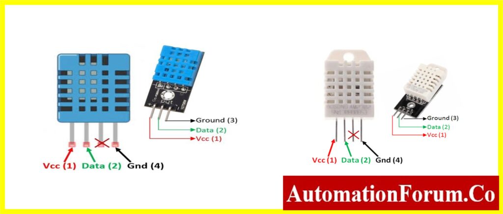
- The Third Section deals with the declaration of variables and defines the pin for the DHT Sensor. There are four pins on the DHT sensor: VCC, Data, NC, and Ground. Each pin of the DHT sensor is connected to the corresponding pin of the Arduino UNO board.

- The next function is the declaration of the pin and type of DHT sensor used under the DHT library. The DHT class is used from the DHT library, dht (object) stores the PIN and type of DHT sensor. (Note: the object can be added any number by adding more DHT sensors)
- The next section deals with the hardware interface to the Arduino board such as LCD, and DHT Sensor. The void setup() with pinMode declaration for the DHT as input.
- The next section deals with the task that Arduino going to perform. In this article, the variable h and t stores the humidity and temperature data. The humidity and temperature extracted by dht(object) are stored in the variables.
- The last section is the final stage of the article, the Display section. The result is shown on the LCD by the display section. The following code will be used to send the different variables that the Arduino has calculated to the LCD. The SetCursor function is used for the starting position and the print function is used for displaying the variable on the LCD screen
Result
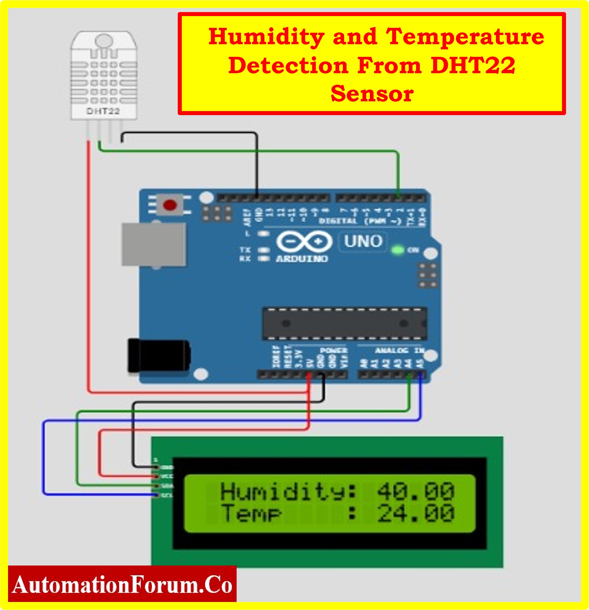
The following images show the Humidity and Temperature measurements using LCD serial communication.

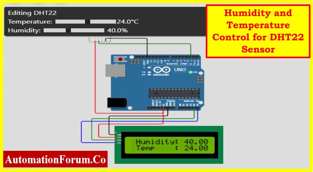
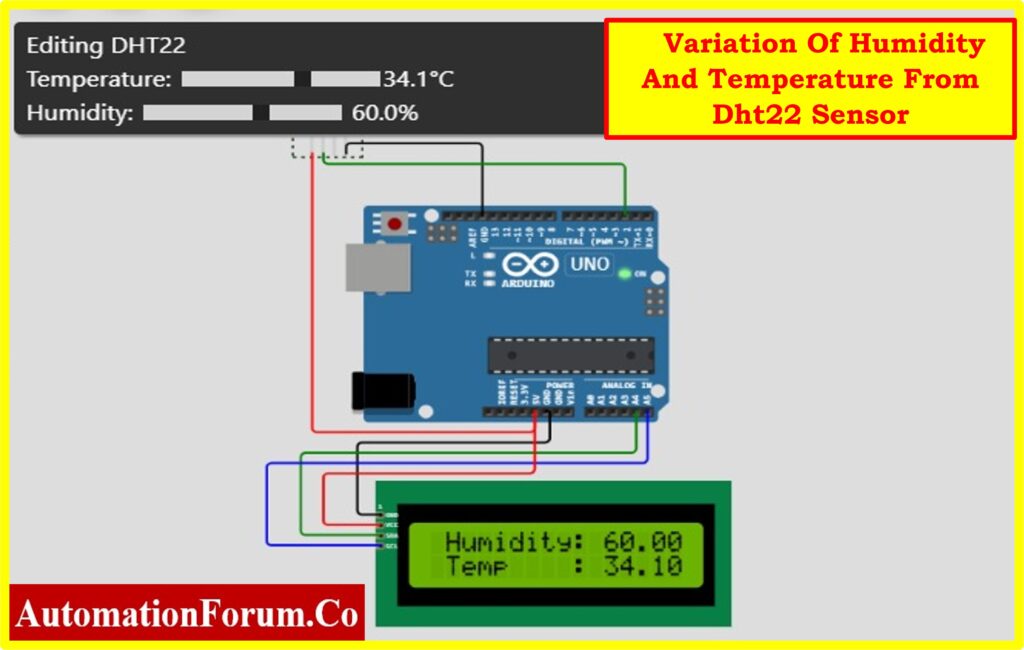
The reader can connect the Arduino UNO to the Serial LCD and DHT22 by completing the aforementioned exercise.