
- Section 1: Overview of SAT for PLC Systems
- Section 2: Pre-SAT Preparation
- Section 3: Power-Up and Initial Checks
- Section 4: System Configuration and Visual Inspection
- Section 5: Power-Up Test for Workstations and Controllers
- Section 6: I/O Loop Testing
- Section 7: Engineering/Operator Station Functionality
- Section 8: Redundancy Testing
- Section 9: Serial Communication Interface Check
- Section 10: Logic Check and System Diagnostics
- Section 11: Environmental Testing
- Section 12: Documentation and Handover
- Downloadable Checklist for SAT Procedures of PLC Systems
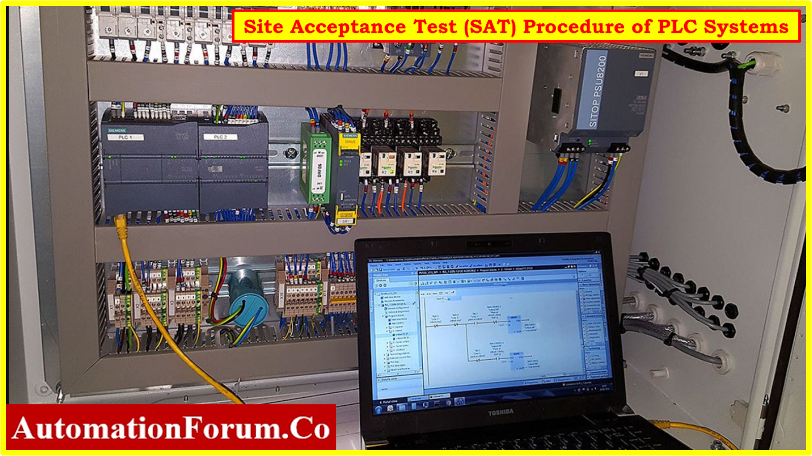
- The Site Acceptance Test (SAT) Procedure of Programmable Logic Controllers (PLC) is a critical phase in the deployment of industrial automation systems.
- This guide presents a comprehensive overview of the SAT process tailored specifically for PLC systems, ensuring thorough testing and verification of functionality at client sites.

Section 1: Overview of SAT for PLC Systems
Definition and Purpose of SAT
- The Site Acceptance Test (SAT) for Programmable Logic Controllers (PLC) is a comprehensive evaluation conducted at the client’s site to verify the functionality, performance, and integration of the PLC system within the industrial environment.
- Its primary purpose is to ensure that the PLC system meets the specified requirements and performs as expected conditions.
Difference between SAT and FAT
- SAT differs from the Factory Acceptance Test (FAT) in that SAT is performed at the client’s site, while FAT takes place at the manufacturer’s facility.
- While FAT verifies the functionality of the PLC system before shipping, SAT validates its performance within the client’s operational context.
Importance of SAT for PLC System Functionality
- Since SAT is the final validation step before the PLC system is implemented, it is extremely important.
- The client gets assurance that the PLC system satisfies their operational requirements and operates reliably in the new facility.
- Additionally, SAT finds any differences between the expected and actual performance of the system, allowing quick correction prior to full deployment.
Key Objectives and Outcomes of SAT Procedure
- Ensure that the PLC system operates as intended and meets the specified functional requirements.
- Validate the integration of the PLC system with existing infrastructure, including sensors, actuators, and other control devices.
- Evaluate the performance metrics of the PLC system, such as response times, accuracy, and reliability, under normal operating conditions.
- Detect and address any discrepancies, errors, or malfunctions in the PLC system’s hardware or software.
- Obtain formal acceptance from the client that the PLC system satisfies their requirements and is ready for operational use.
- Compile comprehensive documentation of SAT results and procedures for future reference. Complete the formal handover of the PLC system to the client upon successful completion of SAT.
Section 2: Pre-SAT Preparation
- To ensure an uninterrupted testing procedure, extensive preparation is required prior to the Site Acceptance Test (SAT) for PLC systems.
- Important actions to take in the lead-up to the SAT are provided in this section:
Gathering Necessary Documents
- Collect essential documents such as electrical drawings, mechanical drawings, P&ID (Piping and Instrumentation Diagram) layouts, and Bill of Materials (BOM).
- These documents provide important insights into the system’s design and specifications, facilitating accurate testing procedures.
Visual Verification of Components and Process Parameters
- Perform a visual inspection to verify that all components and process parameters align with the documentation.
- This step ensures that the PLC system is assembled correctly and in accordance with the specified requirements.
Inspection of Mechanical Components, Fabrication, and Electrical Wiring
- Conduct a detailed inspection of mechanical components, including cabinets, modules, and enclosures, to ensure proper fabrication, alignment and condition.
- Inspect electrical field wiring to verify its integrity, proper termination, and compliance with safety standards. Any deviations or issues should be addressed before proceeding with the SAT.
Verification of Utility Inputs
- Verify utility inputs, such as power and communication lines, provided by the client. Ensure that these inputs meet the system’s requirements in terms of voltage, frequency, and signal integrity.
- Confirm the availability and sufficiency of power sources and communication infrastructure necessary for the operation of the PLC system during the SAT.
Section 3: Power-Up and Initial Checks
- During the Site Acceptance Test (SAT) for PLC systems, the power-up phase is critical for ensuring that the PLC system functions correctly and interfaces properly with peripheral devices.
- This section outlines the essential steps involved in powering up the PLC system and conducting initial checks:
Connection of Main Power Supply to the PLC Panel and Voltage Checks
- Connect the main power supply to the PLC panel as per the electrical drawings and specifications.
- Conduct voltage checks using a multimeter to verify that the incoming voltage levels are within acceptable limits and meet the requirements of the PLC system.
Verification of PLC and HMI/SCADA Communication
- Power up the PLC system and verify communication between the PLC controller and Human Machine Interface (HMI) or Supervisory Control and Data Acquisition (SCADA) system.
- Ensure that data exchange and command transmission between the PLC and HMI/SCADA are established without any errors or interruptions.
Testing of Digital and Analog Inputs and Outputs (IOs) According to Wiring Configurations
- Test digital inputs and outputs (DI/DO) by activating and deactivating input signals and verifying the corresponding output responses.
- Verify the functionality of analog inputs and outputs (AI/AO) by applying test signals within the specified range and observing the PLC’s response.
Adherence to Process Sequence and Interlock Testing
- Follow the predetermined process sequence as outlined in the PLC program logic.
- Conduct interlock testing to ensure that safety and operational interlocks function correctly, preventing potential hazards or unsafe operating conditions.
Section 4: System Configuration and Visual Inspection
- An essential part of the Site Acceptance Test (SAT) is the visual inspection of components and a detailed analysis of the PLC system’s configuration.
- The main procedures for evaluating the system configuration and carrying out visual inspections are described in this section:
Detailed Examination of PLC System Cabinets
- Conduct a careful inspection of the PLC system cabinets to ensure they meet design specifications and standards.
- Verify the integrity of cabinet structures, including dimensions, alignment, and overall condition, ensuring they are free from damage or defects.
Verification of Dimensions, Alignment, and Condition of Cabinets
- Verify that the dimensions and alignment of PLC system cabinets align with the provided specifications and installation requirements.
- Inspect the condition of cabinets, checking for signs of wear, corrosion, or other damage that may impact functionality or safety.
Inspection of Modules, Terminal Blocks, Relays, Isolators, and Wiring Quality
- Inspect individual modules, terminal blocks, relays, and isolators installed within the PLC system cabinets.
- Verify proper installation, secure mounting, and correct labeling of components.
- Assess the quality of wiring, ensuring proper termination, routing, and protection against potential hazards such as short circuits or electrical interference.
Functional Tests for Utility Items and Earthing Inside the PLC Cabinet
- Perform functional tests for utility items such as fans, filters, and other ventilation equipment to ensure proper operation and cooling of the PLC system.
- Verify the effectiveness of earthing systems inside the PLC cabinet to ensure electrical safety and mitigate the risk of electric shock or equipment damage.
Section 5: Power-Up Test for Workstations and Controllers
During the Site Acceptance Test (SAT) for PLC systems, conducting a comprehensive power-up test for workstations and controllers is essential to ensure proper functionality and readiness for operation. This section outlines the key steps involved in the power-up test:
Boot-Up Procedure for Engineering and Operator Workstations
- Initiate the boot-up process for engineering and operator workstations as per the manufacturer’s instructions.
- Allow sufficient time for the workstations to complete the boot-up sequence and initialize all necessary software and applications.
Verification of Workstation Healthiness Indicators
- Verify workstation healthiness indicators to ensure that all components and systems are functioning correctly.
- Check for status indicators, such as LED lights or on-screen messages, indicating successful boot-up and operational readiness.
Installation and Boot-Up Checks for PLC Controllers and I/O Modules
- Install PLC controllers and I/O modules in accordance with the system configuration and installation guidelines.
- Power up the PLC controllers and I/O modules and allow them to complete the boot-up process.
- Verify that all controllers and modules are detected and initialized properly without any errors or faults.
Confirmation of Controller Redundancy and Power Supply Functionality
- Confirm the redundancy configuration of PLC controllers, if applicable, and verify proper failover functionality.
- Test the redundancy mechanism by simulating a controller failure and ensuring seamless transition to the backup controller.
- Verify the functionality of power supplies supplying power to the PLC controllers and modules, ensuring reliability and stability of power distribution.
Section 6: I/O Loop Testing
During the Site Acceptance Test (SAT) for PLC systems, thorough testing of input/output (I/O) loops is crucial to ensure proper functionality and integration with peripheral devices. This section outlines the key steps involved in conducting I/O loop testing:
Verification of I/O Allocation Configuration and Wiring
- Verify the I/O allocation configuration against documentation and system requirements.
- Inspect wiring connections to ensure proper termination and adherence to wiring diagrams.
Loop Testing Procedure for Analog and Digital I/O Loops
- Perform loop testing for analog input/output (AI/AO) and digital input/output (DI/DO) loops.
- Apply test signals to input loops and verify corresponding output responses.
- Test digital loops by activating input signals and confirming correct output states.
- Validate analog loops by checking responses across the specified range.
Recording Observations and Checking Indications in Graphics
- Record observations of loop testing results, including input and output readings.
- Check graphical representations in HMI/SCADA systems to ensure alignment with actual loop events.
- Verify that indications in graphics accurately reflect the status of I/O loops.
Section 7: Engineering/Operator Station Functionality
- During the Site Acceptance Test (SAT) for PLC systems, verifying the functionality of engineering and operator stations is essential to ensure effective monitoring and control of equipment.
- This section outlines the key steps involved in assessing the functionality of engineering and operator stations:
Demonstration of Equipment Monitoring and Control via Graphic Displays
- Showcase the ability of engineering and operator stations to monitor equipment status and performance through graphic displays.
- Verify the visibility and accessibility of critical parameters, such as temperature, pressure, and flow rates, on the graphical interface.
Set Point Adjustment and Control Loop Operation Verification
- Demonstrate the capability of engineering and operator stations to adjust set points and modify control parameters.
- Verify the responsiveness and accuracy of control loop operations, ensuring that changes made through the stations are reflected in the PLC system.
Testing of Process Alarms, Events, and System Alarms
- Test the functionality of process alarms by triggering predefined alarm conditions and verifying their activation on the engineering and operator stations.
- Verify the generation and display of process events, such as equipment malfunctions or status changes, on the graphical interface.
- Confirm the reception and display of system alarms, including critical system notifications and alerts, on the engineering and operator stations.
Section 8: Redundancy Testing
- Redundancy testing is critical to ensure the reliability of the PLC system in case of failures.
- How to conduct thorough redundancy testing is described below:
Testing CPU and Power Supply Redundancy
- Verify the redundancy setup for both CPUs and power supplies.
- Simulate failure scenarios to ensure seamless failover between redundant components.
- Confirm proper alarm notifications for redundancy events to alert operators.
Checks for Diode O-Ring Failure and Controller CPU Loading Limits
- Test for diode O-ring failure by intentionally switching off power supplies and ensuring proper isolation between redundant components.
- Verify controller CPU loading limits to ensure they remain within acceptable thresholds, preventing overloading and degradation of system performance.
Section 9: Serial Communication Interface Check
- Testing the serial communication interface is crucial to ensure smooth data exchange between modules. Here’s a detailed process for conducting this check:
Validation of Module Functionality and Tag Configurations
- Verify the functionality of communication modules to ensure they operate as intended.
- Validate tag configurations to ensure they match the requirements specified in the system design.
Testing of Communication Protocols such as Modbus TCP/IP
- Test the functionality of communication protocols, such as Modbus TCP/IP, by establishing connections between modules.
- Transmit test data packets between modules to verify successful communication.
Simulation of Data Exchange and Verification in Engineering Stations
- Simulate data exchange between modules and verify the reception of transmitted data in engineering stations.
- Validate the accuracy and integrity of the received data in engineering station displays.
Section 10: Logic Check and System Diagnostics
- Ensuring the logic functionality and conducting system diagnostics are essential for maintaining the integrity and reliability of the PLC system. Here’s how to perform thorough checks:
Verification of Logic Functionality
- Compare the logic functionality against control narratives and matrices to ensure alignment with the intended system behavior.
- Test various scenarios and inputs to validate the logic’s response and decision-making process.
System Diagnostic Checks for Process and Safety Systems
- Conduct diagnostic checks for both process and safety systems to identify any potential issues or anomalies.
- Verify the integrity of system components and ensure they are functioning within specified parameters.
Reviewing Status Indicators and Diagnostics in Graphics
- Review status indicators and diagnostics displayed in graphical interfaces to monitor system health and performance.
- Verify the accuracy of status indications and diagnostic messages to promptly address any abnormalities or faults.
Section 11: Environmental Testing
- Environmental testing is vital to assess the PLC system’s performance and reliability under varying conditions. Here’s a concise approach:
Assessment of PLC System Performance
- Test the system under different conditions like temperature, humidity, and vibration.
- Monitor performance during temperature changes and humidity variations.
Verification of System Reliability and Stability
- Conduct stress tests to evaluate system reliability under extreme conditions.
- Monitor system stability over time to ensure consistent performance.
Section 12: Documentation and Handover
- Efficient documentation and handover procedures are essential for concluding the SAT process and transferring the PLC system to the client. Here’s a concise outline:
Compilation of SAT Test Results and Documentation
- Compile concise SAT test results and observations for future reference.
- Document all aspects of the SAT procedure to ensure comprehensive record-keeping.
Conducting IQ, OQ, and PQ Tests with the Client
- Collaborate with the client to conduct Installation Qualification (IQ), Operational Qualification (OQ), and Performance Qualification (PQ) tests.
- Ensure the system meets specified requirements and performance criteria outlined in the documentation.
Final Handover of the PLC System to the Client
- Complete the handover process by providing necessary documentation and certifications.
- Obtain formal acceptance from the client, indicating readiness for operational use.
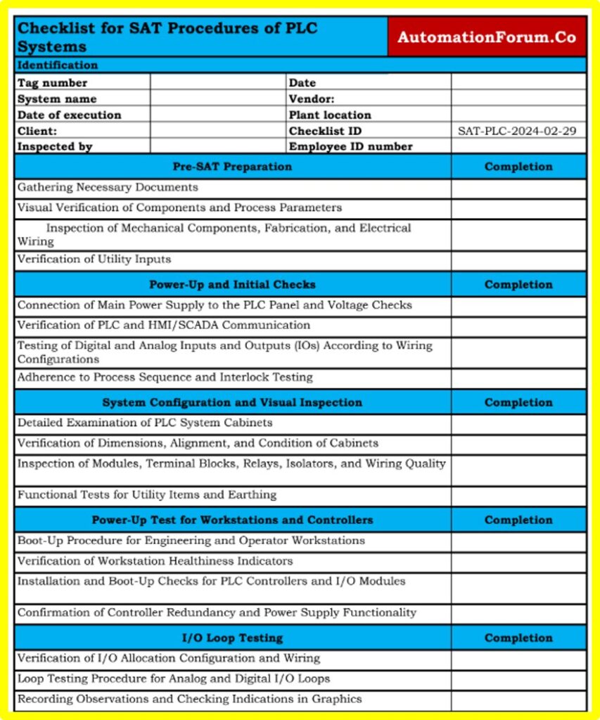
Downloadable Checklist for SAT Procedures of PLC Systems
This below Comprehensive checklist for Site Acceptance Test (SAT) procedures of PLC systems, ensuring thorough verification and documentation.
Click here for A Step-by-Step Basic Guide for Factory Acceptance Test (FAT) of a PLC Panel


